GUI/Docker Reconstruction Workflow
Shared with the CNT
This procedure runs on infrastructure the lab and the CNT operate together. The CNT manual keeps its own copy; changes to the shared steps are agreed with the CNT.
What this page tells you
The easier Docker/GUI route for iEEG reconstruction: same Sectra export and NIfTI conversion, then in iEEG-recon-docker set source directory and sessions, choose Greedy centering and AntsPyNet DKT (radius 2), label electrodes in voxtool, click Run Pipeline, build the ITK-SNAP workspace, upload to PennBox.
-
Open Sectra IDS7 on HUP computer:
- Go to https://pennmedaccess.uphs.upenn.edu → choose Drives & Remote Access under Employee Resources → choose Remote Desktop Connection and open the download
- Computer name: MJ0HKNDA
- Enter your UPHS credentials
- Mount cnt-fs. Instructions: Mounting cnt-fs
- Open PennChart, Dept: Neurology South Pavilion (956)
- Click Chart in the top left corner and find the patient's chart (cross-reference REDCap to find the MRN)
- Click the down arrow at the top right of the screen (below the Log Out button and next to the wrench symbol) → Sectra IDS7
-
Open cnt-fs and create directory to which you will send the imaging:
- Use the UPHS VPN to mount cnt-fs on your desktop
- On the top left of your desktop go to:
- Go → Connect to Server → smb://172.16.50.149/CNT → enter your PMACS username and password
- You are now in cnt-fs. Go To: /imaging_process_fs/imaging_raw/HUP/
- Make a folder called RID###
- Inside this folder:
- Make a folder called preimplant_MRI
- Make a folder called postimplant_CT
-
Export appropriate preimplant images in Sectra:
- In Sectra, right-click on an MRI scan
- Select Export to media
- Click through the different pre-implant MRI scans and use the small arrow on the left to see all of their sequences
- Find the sequence you need.
- Pick a sequence from a recent scan rather than an old one
- You need the MR T1 Axial mprage, which should be isotropic
- A scan without contrast is much better, and PRE is preferred
- PRE means pre-contrast. POST means post-contrast, and wholebrainseg would likely fail on a post-contrast scan
- If no axial mprage fits these criteria, search for Sagittal T1 mprage imaging instead
- Select only the sequence you want
- Uncheck: ‘Include DICOM viewer’ and ‘Include annotations’
- Leave the following checked: ‘Include DICOM images’, ‘Export requests’, ‘Export reports’
- In Destination, select the preimplant_MRI folder you just made in cnt-fs in imaging_process_fs/imaging_raw/HUP/RIDXXX
- cnt-fs must be mounted or this folder will not show up
- Hit Export
-
Export appropriate postimplant images in Sectra:
- Post-implant CT: this should be labeled BONE_AX_HEAD or anything beginning with BONE_AX_
- This image should have at least 120 slices
- Post-implant CT: this should be labeled BONE_AX_HEAD or anything beginning with BONE_AX_
-
- This is the CT scan done on the day of the implant
- If no bone axial exists, let the neuroradiologist know, or call the Pavilion CT Scan Tech to have them make this for you. The number is in Important Contacts & Emergency Numbers
- Right-click on the scan → Export to media
- Select ONLY the bone axial head sequence in the CT
- Uncheck: ‘Include DICOM viewer’ and ‘Include annotations’
- Leave the following checked: ‘Include DICOM images’, ‘Export requests’, ‘Export reports’
-
- In Destination, select the postimplant_CT folder you just made in cnt-fs in imaging_process_fs/imaging_raw/HUP/RIDXXX
* cnt-fs must be mounted or this folder will not show up
- In Destination, select the postimplant_CT folder you just made in cnt-fs in imaging_process_fs/imaging_raw/HUP/RIDXXX
-
- Hit Export
-
Convert from dicom to niftis in Desktop:
- Keep cnt-fs mounted on your desktop
- Open MRIcroGL
- Select Import in the top left
- Select Convert DICOM to NIfTI
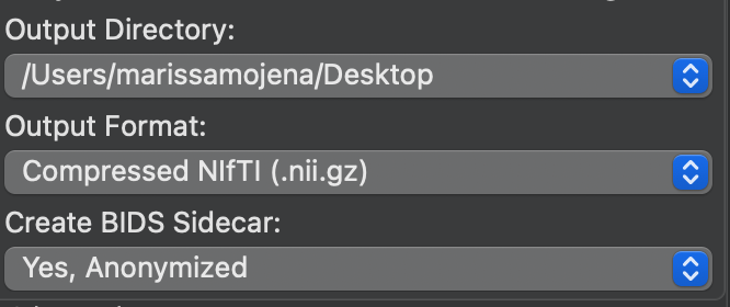
- For the pre-implant MRI, in Output Filename name the file: sub-RID####_ses-clinical01_acq-3D_space-T00mri_T1w
- For the post-implant CT, in Output Filename name the file: sub-RID####_ses-clinical01_acq-3D_space-T01ct_ct
- For Output Directory put your Desktop
- Or you can put it directly into the sub-RIDXXXX folder
- For Output Format leave it as Compressed NIfTI (.nii.gz)
- Example:
-
- In Select Folder to Convert… drag and drop or select the DICOM folder of either the MRI or the CT scan from cnt-fs (postimplant_CT or preimplant_MRI) into the space that says “Drop files/folders to convert here”
* The spinning rainbow wheel means that MRIcroGL is converting
- In Select Folder to Convert… drag and drop or select the DICOM folder of either the MRI or the CT scan from cnt-fs (postimplant_CT or preimplant_MRI) into the space that says “Drop files/folders to convert here”
- Now that the converted niftis are made, create the following folders and put the niftis in the sub-RIDXXXX/ses-clinical01 folder on your Desktop:
- Put the MRI NIfTI in the folder called anat
- Put the CT NIfTI in the folder called ct
- Once you label the electrodes, the electrode coordinates will go in the folder called ieeg
- Parent folder: sub-RID####
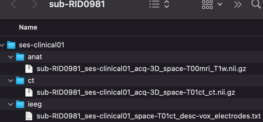
- Sub-folder: ses-clinical01
- anat
- sub-RID####_ses-clinical01_acq-3D_space-T00mri_T1w.nii.gz
- ct
- sub-RID####_ses-clinical01_acq-3D_space-T01ct_ct.nii.gz
- ieeg
- sub-RID####_ses-clinical01_space-T01ct_desc-vox_electrodes.txt
- anat
- Sub-folder: ses-clinical01
Open iEEG-recon-docker
- Click 'browse' and point the GUI to where your sub_RID### folder is stored (for example Downloads or Desktop)
- It should find your sub-RID### folder
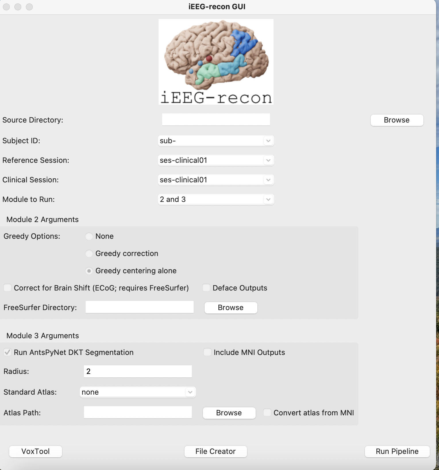
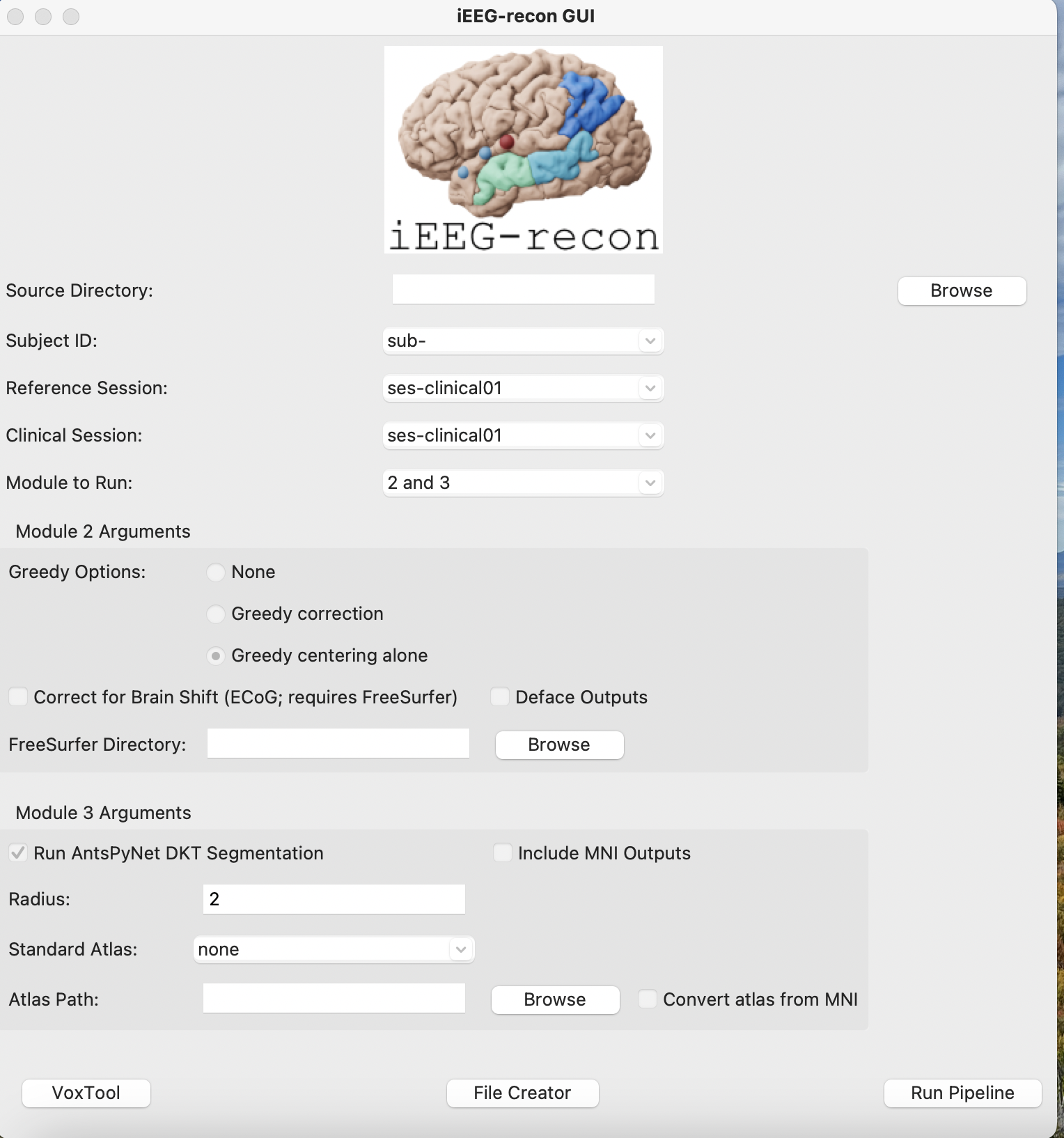 source directory: sub-RID## folder pathway
subject ID: sub-RID###
reference session: ses-clinical01
clinical session: ses-clinical01
Greedy Options:
- check: Greedy centering alone
Module 3 Arguments:
- check: Run AntsPyNet DKT Segmentation
- Radius: 2
- Standard Atlas: none
- Atlas Path: leave blank
Now click Voxtool in the lower left corner.
- This opens Voxtool
- Load in the post-implant CT NIfTI:
- Click “Load Scan” in the lower left corner of the application
- Select the post-implant CT NIfTI that you just made
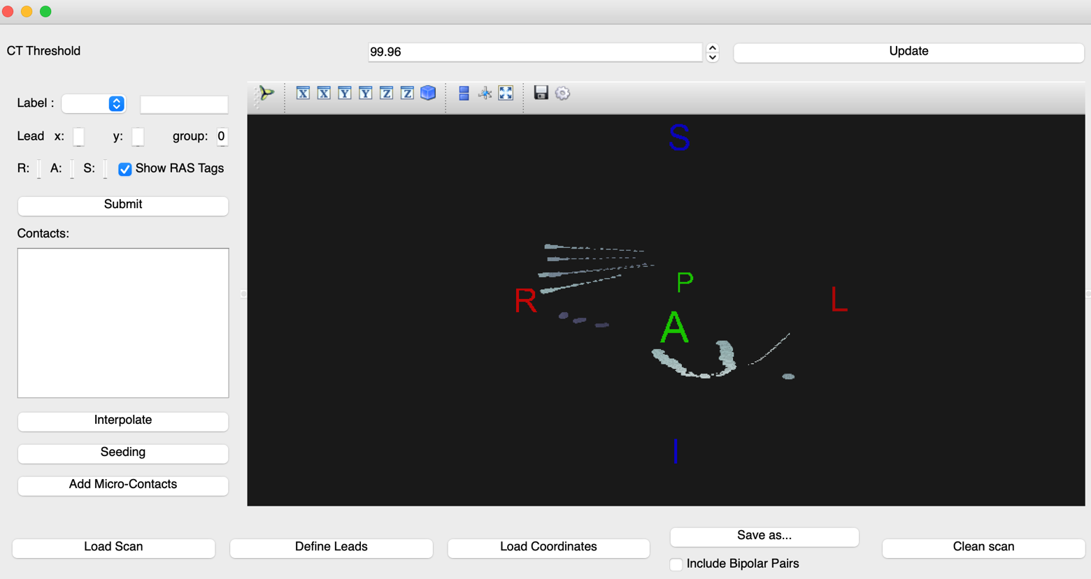
- The CT image should appear within the black space
- Check for display abnormalities: compressed CT, incorrect orientation of superior/inferior, anterior/posterior, and right/left
- If the CT image has high impedance, you can adjust the threshold from the original 99.96 to a more suitable threshold (for example 99.94 or 99.98)
- When saving the completed electrode labels, the threshold MUST be returned to 99.96. Pre-save the coordinates at your labeled threshold to fill in any blanks if they get erased when returning to the original 99.96
- When saving the completed electrode labels, the threshold MUST be returned to 99.96. Pre-save the coordinates at your labeled threshold to fill in any blanks if they get erased when returning to the original 99.96
- If the CT image has high impedance, you can adjust the threshold from the original 99.96 to a more suitable threshold (for example 99.94 or 99.98)
- Check for display abnormalities: compressed CT, incorrect orientation of superior/inferior, anterior/posterior, and right/left
-
Define leads as specified by the clinic map
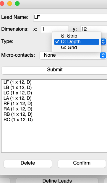
- Click “Define Leads” on the lower left section of the application and a pop-up will appear
- Select the lead “Type”: currently Penn is only using Depth electrodes
- “Lead name” is listed in the implant map as an abbreviation. Dimensions is the number of contacts per implanted electrode
- Click “Define Leads” on the lower left section of the application and a pop-up will appear
-
-
- The X coordinate is the point closest to the center of the brain and should always be 1
* The Y coordinate is the point closest to the skull and should be the maximum number of contacts within that electrode
* After each lead name and dimension is entered, select Submit to save this parameter
* You can check whether each lead has been entered with the correct number of electrodes in the display area under the Submit tab.
* When this process is done, click Confirm
- The X coordinate is the point closest to the center of the brain and should always be 1
-
Labeling
-
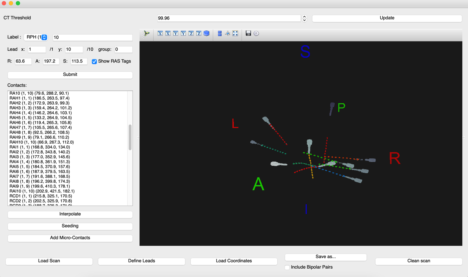
- Begin labeling by selecting the label name from the drop-down menu
- First pick a distinguishable electrode on the map/CT scan to begin with
- Once you locate that electrode, click on the contact that is closest to the center of the brain and click Submit. This will automatically be label 1.
- The next label in the “Label” column and the Y coordinate in the “Lead” column will now change to 2, meaning the 2nd contact of that electrode.
- Change the label and Y coordinate to 12 to denote that you are labeling the last contact, the one closest to the skull. (In this example the last point is the 12th contact. If the total number of contacts is different, change these labels to that number.)
- Count the remaining contacts of the electrode, select the final contact point, then click Submit
- When the first and last contacts have been labeled, click “Interpolate” to auto-calculate the coordinates of the remaining contacts
- If a label does not interpolate, the electrode may be curved and will need to be labeled manually
- Find the contact number by counting from the point closest to the center of the brain (point 1) up to the unlabeled contact
- Enter the number of the unlabeled contact in the “Label:” row and again in the “Y:” coordinate space
- Select that contact, then select “submit”
- If you are clicking and nothing is registered, check the terminal to see whether your mouse clicks are being registered
- If they are not, exit and start the process again by reloading the CT image and entering the electrodes/contacts
 Save the file
- If a label does not interpolate, the electrode may be curved and will need to be labeled manually
-
- To save the completed labeling, select “Save as…”
* Change the file name to sub-RID####_ses-clinical01_space-T01ct_desc-vox_electrodes
*
- To save the completed labeling, select “Save as…”
-
Select the folder where the labels should export (sub-RID####/ses-clinical01/ieeg)
- Set the file type to “ TXT (*.txt) “
Running Pipeline-
- Exit Voxtool
- You should be back in the iEEG-recon GUI screen
- In the bottom right, click "run pipeline"
- Make sure the Docker app is open
- Make sure the terminal is open and running
- The pipeline now runs automatically
- It says "successfully completed!" when finished
-
Check the sub-RID### folder for a derivatives folder, which will have a module 2 folder
-
If Module 3 does not run, run the reconstruction on Borel instead (Part III of Electrode Reconstruction: Prep & Software)
PART IV: Create ITK-SNAP Workspace
- Go to the module2 folder in your Downloads (sub-RID####/ses-clinical01/derivatives/ieeg_recon/module2)
- Right-click on the sub-RID####_ses-clinical01_itksnap_workspace.itksnap file and open it in ITK-SNAP (this file has the red ITK-SNAP icon next to it)
- Scroll through to make sure the colored electrode coordinates line up with the coregistered MRI/CT
- Import the label descriptions so that electrode names are visible when hovering over each coordinate
- Click Segmentation and scroll to Import Label Descriptions
- The Open Label Descriptions pop-up will prompt you to specify the label description file
- Click Browse and select sub-RID####_ses-clinical01_space-T01ct_desc-vox_electrodes_itk_snap_labels.txt
- Save the ITK-SNAP file with these edits.
- Upload the reconstruction to the PennBox CNT Implant Reconstructions folder.
- Go to the CNT Implant Reconstructions folder
- Make a folder called RIDXXX_HUPXXX
- Go into this folder
- Drag and drop the entire sub-RIDXXXX folder into this PennBox folder
- Upload the HUPXXX_anon implant map PDF into this folder as well
If the workspace file does not open correctly, try these steps:
- Load "sub-RID####_ses-clinical01_acq-3D_space-T01ct_T1w.nii.gz" into ITK-SNAP
- Load "sub-RID####_ses-clinical01_acq-3D_space-T01ct_ct_ras_thresholded.nii.gz" as another image
- Load "sub-RID####_ses-clinical01_acq-3D_space-T01ct_ct_ras_electrode_spheres.nii.gz" as a segmentation
- Save everything as a workspace
Part V: Send email to Clinical Team to notify reconstruction is complete and ready to access
- Create a shared link to the subject folder in Penn Box and set it so that anyone with the link can view and download (Pennbox Folder: CNT Implant Reconstructions)
- Only from a PennMedicine email account, send this link to the Epilepsy MDs NPs group and to the Epilepsy Fellows group, and cc the neuroradiologist and your co-CRC